A valuable automobile analogy for quick and cost-effective electronic design
26 Feb 2019
Imagine we wanted to design a competitive automobile product.
For its target selling price, we would want to make it as powerful, high-performance, quiet, and easy to drive as we can achieve in the too-short timescale we have been allowed.
Operation of its throttle and brake pedals, steering wheel, engine, transmission, suspension and wheels, steering gear, brakes, etc. applies mechanical forces to/from each other, and to/from the outside world via its wheels.
So – we always start off with a single common mechanical structure, on which to fix all these items. This structure must be as stiff and strong as we can afford, considering the mechanical forces it must handle.
For the same reasons, we also need to make sure that its throttle and brake pedals, steering wheel, engine, transmission, suspension and wheels, steering gear, brakes, etc. are all firmly fixed to the common structure.
Some of the fixings can be direct (bolts, welds, etc.) but some have to be indirect (joints, bushes, rubber mountings, etc.).
Without this good starting point we stand no chance of achieving good performance and handling for the price, in the timescale, whatever else we do! So, it is important to invest enough in the mechanical structure, and how things are fixed to it, right from the start of the project.
The outside world that our vehicle connects to via its wheels is rough and bumpy, so for quietness their suspension must isolate that noise from our vehicle’s structure as much as possible, but without causing its handling to suffer too much. This is quite a challenging design issue!
Now, imagine we wanted to design a competitive electronic product.
For its target selling price, we would want to make it as powerful, high-performance, quiet and easy to control as we can achieve in the too-short timescale we have been allowed.
Operation of its sensors, controls, power controllers, loads, filters, I/O cables, etc., applies electrical forces to/from each other, and to/from the outside world via its I/O cables.
So – we always start off with a single common electrical structure, on which to fix all these items. This structure must be as stiff and strong as we can afford, considering the electrical forces it must handle.
(The electrical equivalent of ‘stiff and strong’ is: maintaining a low-enough impedance from DC up to a high-enough frequency. We can generally only do this by using metal planes or metal enclosures.)
For the same reasons, we also need to make sure that its sensors, controls, power controllers, loads, filters, I/O cables, etc. are all firmly connected to the common electrical structure.
Some of the connections can be direct (bolts, welds, solder, etc.) but some have to be indirect (e.g. filter or decoupling capacitors, etc.).
Without this good starting point we stand no chance of achieving good performance and ease of control, in the timescale, whatever else we do! So it is important to invest enough in the electrical structure and how things are connected to it, right from the start of the project.
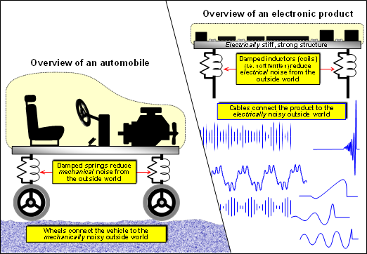
The outside world that our product connects to via its ‘wheels’, i.e. its I/O cables, is very electrical noisy, so for quietness their filters must isolate that noise from our product’s electrical structure as much as possible, but without causing its electrical/electronic performance to suffer too much. This is quite a challenging design compromise!
A vehicle’s suspension arm needs a spring, but a spring with mass on its end will resonate and cause handling problems so it needs damping with resistance (usually a hydraulic ‘resistance’).
Interestingly, the best way for an electronic unit to communicate with its external inputs and outputs is also via a damped spring – a soft ferrite choke (which has electrical resistance)!
Conclusions
The best way to design a competitive automobile product, is to start its project by ensuring that everything is firmly fixed to a single stiff strong mechanical structure, connected to the noisy outside world via wheels that are fixed to suspension that uses damped springs.
The best way to design a competitive electronic product, is to start its project by ensuring that everything is firmly connected to a single low impedance electrical structure, connected to the noisy outside world via cables fitted with filters that use damped inductors.
An example of how powerful and valuable this analogy is:
If we have an electronic product that comprises two or more PCBs, we should certainly make sure that each of them a low-impedance Reference plane. But when interconnecting two or more PCBs together we must either:
- Create an electrical bond between them that maintains a low-enough impedance from DC up to a high-enough frequency, so their assembly behaves as a single solid structure.
This generally needs interconnecting planes; or multiple low-impedance fixings between each PCB’s Reference plane and the wall or base of a single metal enclosure.
- Treat each PCB as an electronic product in its own right, and only connect to the other PCBs via filtered I/O cables – treating them exactly as if they were ‘outside worlds’.
Most of the EMC problems that I have seen in many hundreds of electronic products that comprise two or more PCBs, were caused by ignoring both i) and ii) above.
Applying this simple automobile analogy instantly reveals why these problems arose.
We only need imagine how a vehicle would perform if its front half was only loosely connected to its rear half!
Note: In the above example I used the term ‘Reference plane’, for what is often called an Earth, Ground, or GND plane. I don’t like the terms Earth, Ground, or GND, or their respective drawing symbols, because they are often confused with safety earths or grounds and the resulting confusion causes the worldwide electronics industry to waste a great deal of time and money every year.
Caveats
This analogy is very good, and I use it a lot because most engineers are so familiar with vehicles that they ‘get it’ instantly.
But of course, like any analogy, it can’t possibly be comprehensive, so should be used with that understanding. For example: it doesn’t hold for shielded cables, wireless communications, external power sources, and much else.
Some useful references:
[1] “Segregation and Interface analysis”, the second in a series of eight articles on good-practice EMC design techniques for printed circuit board (PCB) design and layout, free download from https://www.emcstandards.co.uk/part-2-segregation-and-interface-analysis
[2] “EMC techniques in electronic design Part 5 - Printed Circuit Board (PCB) Design and Layout”, the fifth in a series of six articles on basic good-practice electromagnetic compatibility (EMC) techniques in electronic design, free download from https://www.emcstandards.co.uk/design-techniques-for-emc-part-5-printed-circui
[3] “EMC for Printed Circuit Boards”, a textbook by Keith Armstrong, only available to buy from: https://www.emcstandards.co.uk/emc-for-printed-circuit-boards
[4] “EMC Design Techniques for electronic engineers”, a textbook by Keith Armstrong, only available to buy from: https://www.emcstandards.co.uk/emc-design-techniques
[5] “Analogue design techniques for S/N (SNR) and immunity to EMI”, Keith’s up-to-date training coursenotes, only available to buy from: https://www.emcstandards.co.uk/analogue-design-techniques-for-sn-snr-and-imm
[6] “Module 6A, Essential PCB design techniques for cost-effective SI, PI, EMC”, Keith’s up-to-date training coursenotes, only available to buy from: https://www.emcstandards.co.uk/essential-pcb-designlayout-techniques-for-cost
[7] “Good EMC Engineering Practices in the Design and Construction of Industrial Cabinets”, free download: https://www.emcstandards.co.uk/good-emc-engineering-practices-in-the-design-an1
[8] “Good EMC Engineering Practices for Fixed Installation”, free download: https://www.emcstandards.co.uk/good-emc-engineering-practices-for-fixed-instal2
[9] “EMC for Systems and Installations”, ISBN 0-7506-4167-3, by Tim Williams and Keith Armstrong, available to buy from: https://www.emcstandards.co.uk/emc-for-systems-and-installations2
[10] “Good EMC Engineering practices for electrical cabinets systems and installations”, Keith’s up-to-date training coursenotes, only available to buy from: https://www.emcstandards.co.uk/good-enc-engineering-practices-for-electricalel
Get more from EMC Standards
EMC Standards is a world-leading resource for all things EMC and EMI related. Our website is packed full of both free and paid-for content, including:
- Online quiz
- Webinars
- Training quiz
- And much more!

Electromagnetic Engineering (EMgineering) is the basis for proven good design practices for signal integrity (SI), power integrity (PI), and the control of EMI emissions and immunity (EMC).
Our aim is to help people learn how to more quickly and cost-effectively design and manufacture electronic equipment (products, systems, installations, etc.) to meet functional (i.e. SI/PI) specifications and conform to EMC standards, directives and other requirements.
Such equipment should benefit from reduced warranty costs and financial risks, whilst improving uptime, competitiveness and profitability.
We also cover basic good electrical safety engineering; and the Risk Management of Electromagnetic Disturbances / EMI, whether for Functional Safety or other types of risk.
Join EMC standards TODAY!