Where best to place CM chokes on VSD motor cables?

11 Sep 2023
Where best to place CM chokes on VSD motor cables?
Most EMC guidance says Common Mode (CM) Radio Frequency (RF) noise suppression chokes should be placed around the outside of shielded (i.e. screened) cables. But to reduce the RF emissions from the motor cables of modern Variable Speed Drives (VSDs), this is usually not the best approach.
Modern VSDs use very fast high-power semiconductor switching devices to deliver pulse-width-modulated (PWM) voltages to the motor terminals, relying on the naturally high inductance of the motor’s coil windings to integrate the “EMC nasty” waveforms into the smooth-ish sinusoidal magnetic flux waveforms that the motor needs to make it rotate.
Figure 1 sketches a PWM voltage (V, in blue) giving rise to an approximately sine-wave magnetic flux (B, in red) in a motor winding. The red ‘B’ curve has the same shape as VSD output current that flows in the winding.
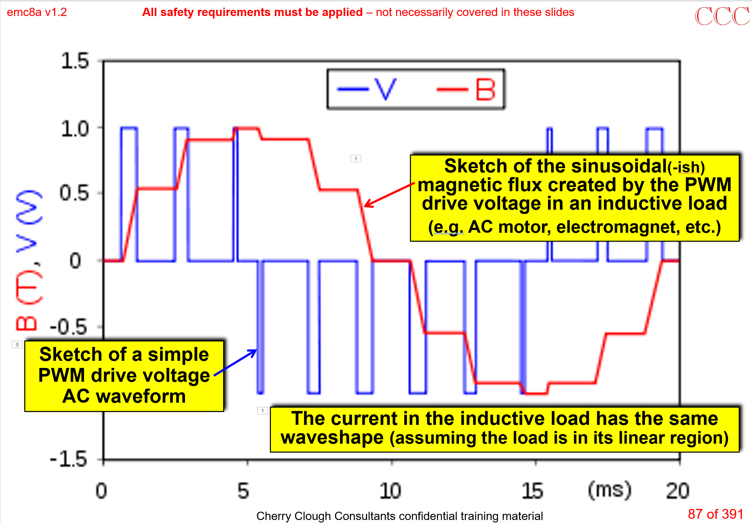
Figure 1: Simplified example of a PWM switching waveform being reconstructed into a sinewave current and B-field in a sufficiently large load inductance
Figure 1 looks very clean and nice because it is an instructional sketch, whilst Figure 2 is an example of what you might see in practice.
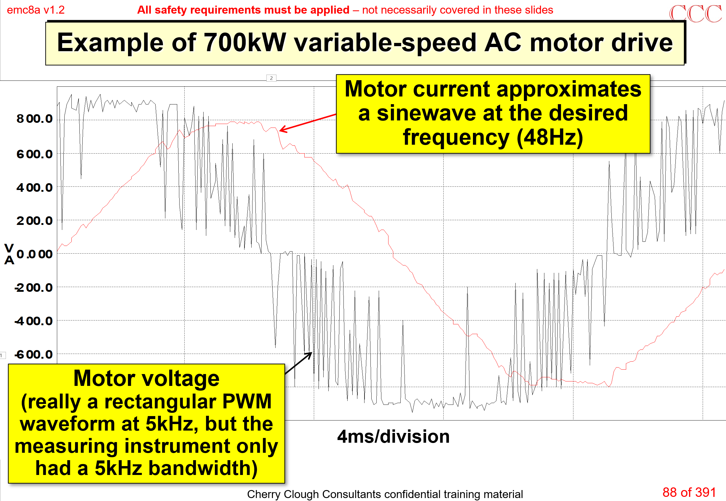
Figure 2: An actual measurement of motor current with PWM VSD
Both Figures 1 and 2 show the Differential-Mode (DM) power that we use to spin the motor. Unfortunately, we can’t entirely avoid having imperfections – stray resistances, capacitances and inductances – in the motor cable’s conductors; the motor’s windings and metal frame, and not least within the VSD itself. These imperfections cause unwanted stray currents to flow in them all, which we call “Common-Mode” (CM) noises.
VSD systems are very powerful, so create very large CM currents! These CM noise currents are the main causes of the RF emissions that make them fail EMC compliance tests.
Ideally, using a shielded motor cable provides a low-enough impedance path for the CM noise currents to ‘encourage’ enough of them to flow on the inside surfaces of the motor cable’s shield, thereby shielding it from causing excessive RF emissions. This path is outlined as the red ellipse that is most towards the right hand side of Figure 3.
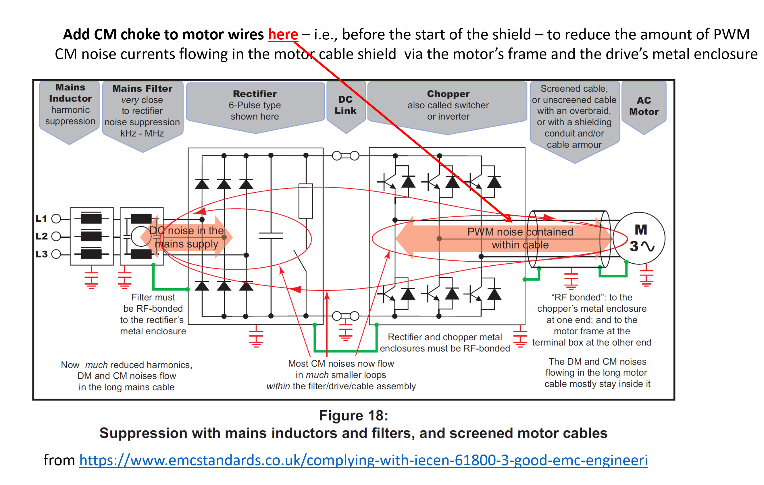
Figure 3: from REO (UK)’s guide on complying with the EMC standard for motor drive systems, EN/IEC 61800-3
Unfortunately, the real world is far from ideal, and people often terminate industrial motor cable shields badly, for example by:
- Using lengths of wire, often called ‘pigtails’ (note: using green/yellow insulation does not help!)
- Leaving one end of the shield unterminated, through a mistaken fear of (so-called) ground loops.
The unbreakable laws of nature, and of electromagnetic propagation, ensure that all currents always flow in closed loops – even stray CM noise currents.
So a ground loop is exactly what we need in this situation, to encourage the stray CM noise currents induced into the motor’s metalwork to close their loops all the way back to the VSD via the inner surface of the motor cable’s shield so as to cause much lower RF emissions!
But in real industrial applications, cable shields and their terminations tend to be low-cost and far from ideal, even if they happen to be assembled correctly. So, Figure 3 also shows the best location for adding a CM choke: inbetween the VSD’s PWM output and the start of the motor cable’s shield.
In this location, the CM choke will significantly reduce the amount of CM noise currents that flow from the VSD to the motor, which cause RF emissions as they (inevitably) close their current loops back to the VSD. Figure 4 illustrates a practical example of such a construction, taken from a real VSD cabinet in the mid-1990s.
Putting a CM choke over the shielded section of motor cable instead, should reduce the amount of CM noise currents that flow in loops via the motor’s external metal support structures, and the structure of the building, vessel or vehicle. But – so far – I’ve always found that doing that was less effective than fitting the CM choke on the VSD’s output to the motor cable before the start of its shielding, as shown in Figures 3 and 4.
But my long experience doesn’t mean it will always be like that.
VSD installations are very varied, so it’s worth allowing for fitting CM chokes in both locations, then experimenting with some CM chokes in the actual installation while checking the RF emissions to see which arrangement is best.
You might even find that sometimes the best results need CM chokes in both locations! In which case I recommend checking the assembly of the motor cable’s shield terminations – at both ends.
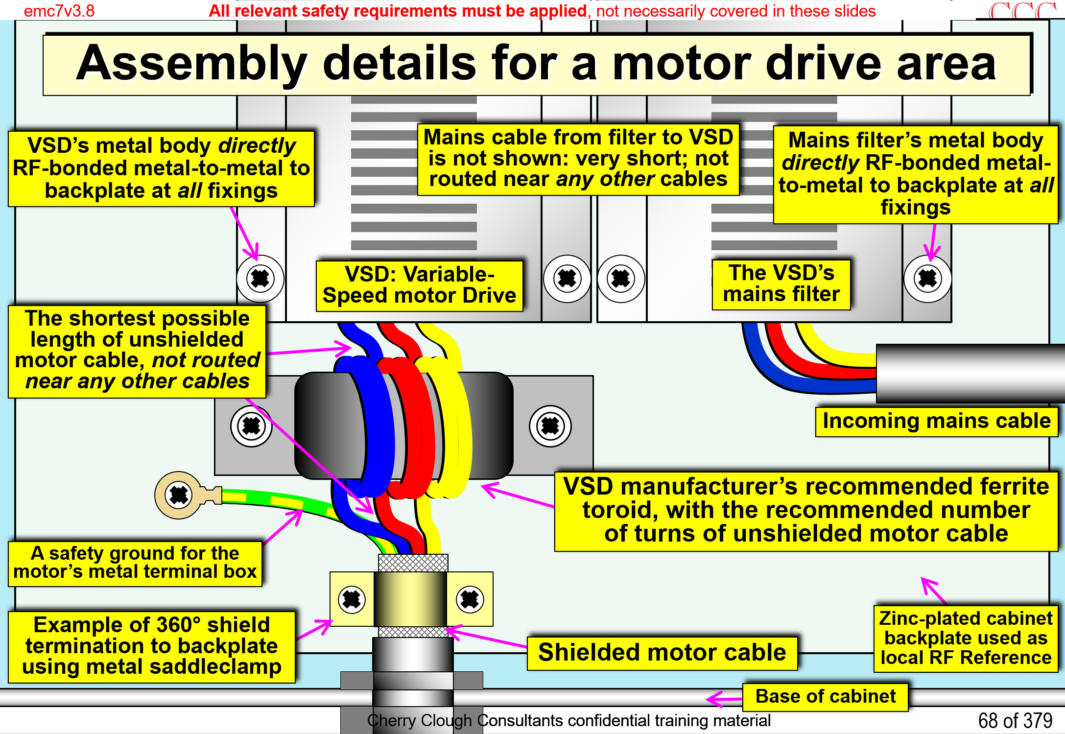
Figure 4: A practical example of adding a CM choke to a shielded motor cable, to reduce the RF emissions from a VSD system
Now, “checking the RF emissions” of a VSD system in a real-life sounds like it should be difficult, costly, and time-consuming – all of which will be true if you ask an EMC test laboratory to do it, because they will do it accurately to the relevant EMC test standards.
But, unless we want an EMC Site Survey for legal compliance reasons, we generally don’t need such accurate on-site EMC testing. Finding the best locations for CM chokes, and/or the best methods for terminating the shields of motor cables, is quick and easy to do with low-cost portable equipment, as shown in Figure 5.
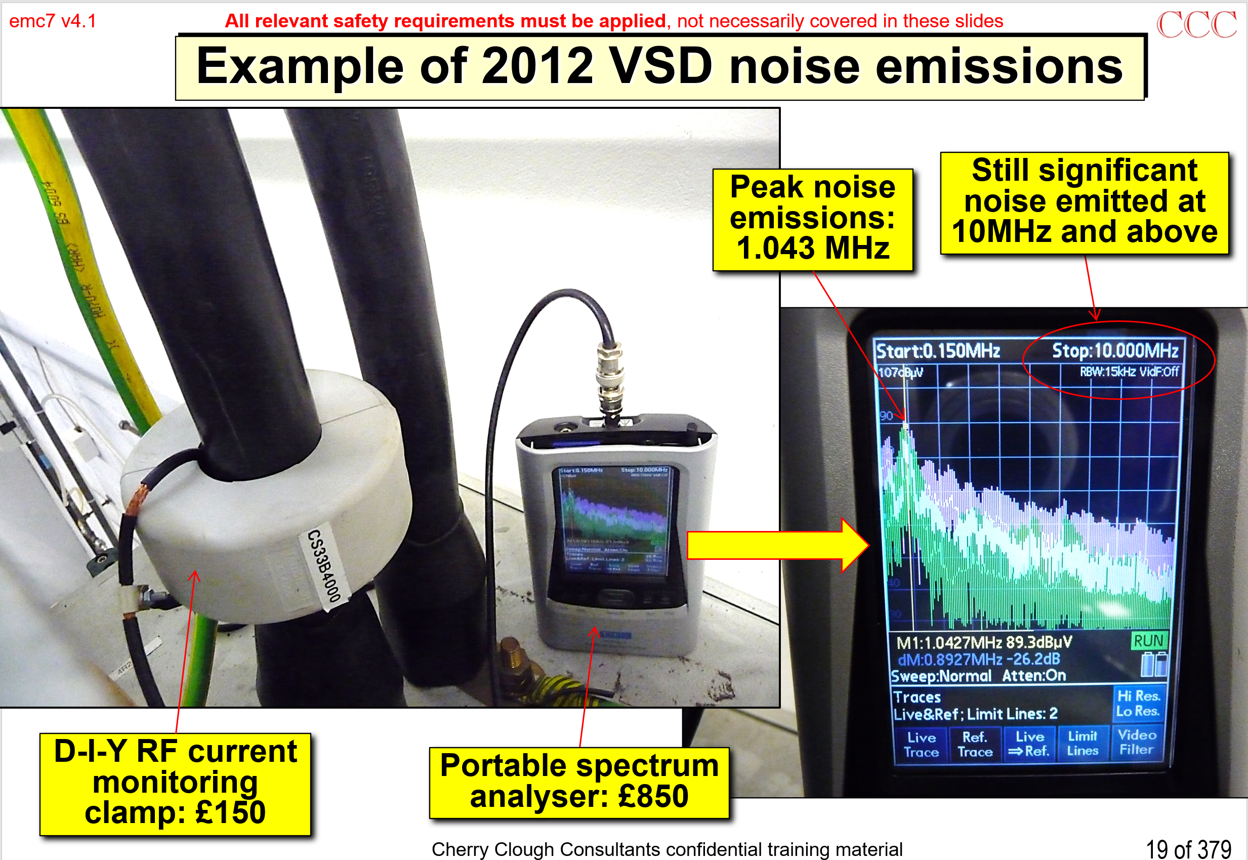
Figure 5: An example of easily checking a VSD system’s RF emissions
Taken from my course on good EMC engineering for cabinets, systems and installations, available as colour coursenotes from https://www.emcstandards.co.uk/emc-for-systems-installations2 and as a video webinar from https://emcstandards-shop.fedevel.education
For more on easy, quick, low-cost EMC checking (and even easy, quick, low-cost pre-compliance EMC testing) see the section on “RF Current Monitor Probing” in my training course on using near-field probing (also called close-field probing), available as colour coursenotes from https://www.emcstandards.co.uk/cost-effective-uses-of-close-field-probing1, and as a video webinar from https://emcstandards-shop.fedevel.education.
Get more from EMC Standards
EMC Standards is a world-leading resource for all things EMC and EMI related. Our website is packed full of both free and paid-for content, including:
- Online quiz
- Webinars
- Training quiz
- And much more!

Electromagnetic Engineering (EMgineering) is the basis for proven good design practices for signal integrity (SI), power integrity (PI), and the control of EMI emissions and immunity (EMC).
Our aim is to help people learn how to more quickly and cost-effectively design and manufacture electronic equipment (products, systems, installations, etc.) to meet functional (i.e. SI/PI) specifications and conform to EMC standards, directives and other requirements.
Such equipment should benefit from reduced warranty costs and financial risks, whilst improving uptime, competitiveness and profitability.
We also cover basic good electrical safety engineering; and the Risk Management of Electromagnetic Disturbances / EMI, whether for Functional Safety or other types of risk.
Join EMC standards TODAY!