Validation of ESD Current Waveform Using an RF Current Probe

04 Dec 2023
Introduction:
In the realm of EMC consulting, addressing Electrostatic Discharge (ESD) related issues is a common task. While the use of an ESD simulator greatly aids in troubleshooting, it's imperative to ensure that the simulator discharges a current waveform in accordance with the standard. Deviations from the standard waveform can lead to challenges such as difficulty in issue identification (if the waveform is too weak) or proposing overly engineering solutions (if the waveform is too strong).
To mitigate such uncertainties, performing a quick and efficient sanity check of the ESD waveform becomes crucial. This article explores a method for conducting this check, initially proposed by D. Smith in [1]-[3]. The objective is to verify whether the ESD simulator produces a current waveform that aligns with expectations.
Test Setup:
The test setup employed for this validation consists of the following components:
- Two Ground Planes: One vertical and one horizontal.
- Ground Leads to Earth.
- Tekbox RF Current Monitoring Probe TBCP2-750.
- Oscilloscopes: Agilent Infiniium 54845A (1.5GHz bandwidth) & Rigol DS7054 (500 MHz).
- 20dB Attenuators: Mini-circuits & Tekbox.
- ESD Simulators: Schlöder SESD 200 & Keytek Minizap.
- Coaxial Cable: Tekbox RG316, with ferrite cores (TDK ZCAT1325-0530A).
Testing Approach:
Unlike conventional ESD testing setups that strictly adhere to standard protocols, this method provides a rapid check. It allows us to quickly determine whether the ESD simulator's current waveform aligns with expectations. Typically, heavily used ESD simulators may exhibit waveform distortion, characterized by inadequate rise peaks or irregularities in the low-frequency "hump."
The basic setup involves two ground planes—one horizontal and one vertical. The horizontal ground plane is connected to earth via two 470 k Ω resistors, although earthing the horizontal plane directly has proven effective in practice.
Test Procedure:
- Position the current probe close to the edge of the test ground plane, with only half of the probe on the plane and the other half in free space. This minimizes common-mode ESD current traveling along the coaxial shield to the scope.
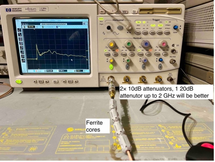
- Employ ferrite cores on the coaxial cable at the scope to suppress common-mode ESD currents.
- Use a short, well-shielded coaxial cable (in this case, RG-316) for accurate results. The better the shielding effectiveness of the coaxial cable, the better.
- The ESD simulator’s grounding lead is connected to the horizontal ground plane on the wood table instead of earthing to the floor Reference Ground Plane.
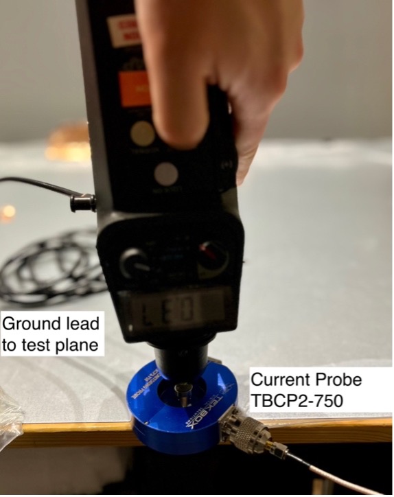
Figure 1. Test Set-up
the oscilloscope side
20dB Attenuation:
Smith has been utilizing the Fischer FCC F-65 probe, whereas I have opted for the Tekbox TBCP2-750 probe. It was important for me to ascertain whether the use of the TBCP2-750 would yield comparable results. The Tekbox TBCP2-750 can operate within a 1 GHz frequency range and boasts a transfer impedance of 20 dBΩ. In fact, the 3 dB bandwidth is typically 850 MHz, as the transfer impedance curve is shown in Figure 2. While a transfer impedance of 20 dBΩ renders the probe more sensitive, allowing for higher voltage readings for the same current magnitude, it introduces a challenge when connecting to an oscilloscope with a 50Ω input impedance. This is due to the fact that most oscilloscopes with a 50 Ω input impedance impose an upper limit on the maximum input voltage, typically around 5V RMS. Consequently, when dealing with a 3 A peak current, the voltage measured by a TBCP2-750 probe can surge to approximately 30 V (given that 20dBΩ is equivalent to 10Ω (=1V/A in the flat region in the transfer impedance curve)). This voltage level substantially exceeds the oscilloscope’s upper limit.
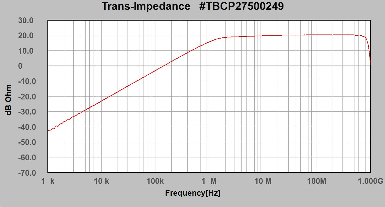
Figure 2. Transfer impedance of TBCP2-750 RF Current Probe
To address this, an external 20dB attenuator is therefore used. This modification results in an effective transfer impedance of 0dBΩ (1Ω). Consequently, voltage measurements on the oscilloscope accurately represent the current (1V = 1A×1Ω).
Considerations:
In order to achieve a good performance, use a coaxial cable and attenuator specified to 6 GHz.
Waveform Validation:
The primary objective of this test is to conduct a sanity check, focusing on waveform reliability and shape, rather than adhering strictly to standard waveforms. A comparison of our setup with D. Smith’s results, as presented in his papers, allows us to assess any deviations.
Performing a 1kV contact discharge with the current probe connected to the oscilloscope’s 50Ω input via two 10dB attenuators (a 20dB attenuator would offer better performance) yielded results. The waveforms obtained from both ESD simulators under test were compared to D. Smith’s curve. As can be seen in the figure, A 1kV contact discharge using a 150 pF/330 Ohm network results in a peak current at about 3.5 Amp to 4 Amp. It is also interesting to note that the low-frequency hump is about 2 Amp, which aligns with Smith’s results. The horizontal scale is 10 ns/div, the vertical scale is set 1V/div, as mentioned previously, in this set-up, 1V equals 1Amp current. The results of our tests closely matched D. Smith’s findings, affirming that our setup is suitable for conducting a quick sanity check of an ESD simulator’s performance.
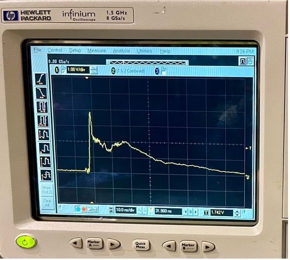
Figure 3 Results Analysis (a) Minizap with IEC Omni Tip 1kV contact discharge current waveform
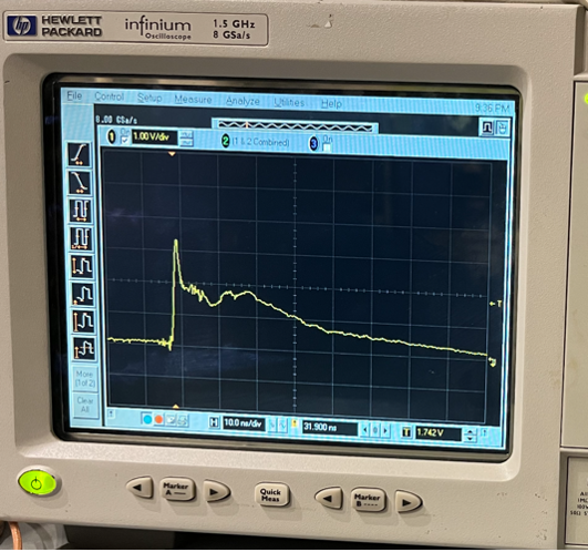
(b)Schlöder 1kV contact discharge current waveform
Further Testing:
In addition to our initial validation, we conducted further tests to explore various scenarios, including the use of a 20dB attenuator from Tekbox and testing with an RG58 coaxial cable. A slower oscilloscope (Rigol DS7054, 500 MHz bandwidth) was also used in a comparison test. These additional tests aimed to provide a comprehensive evaluation of our methodology.
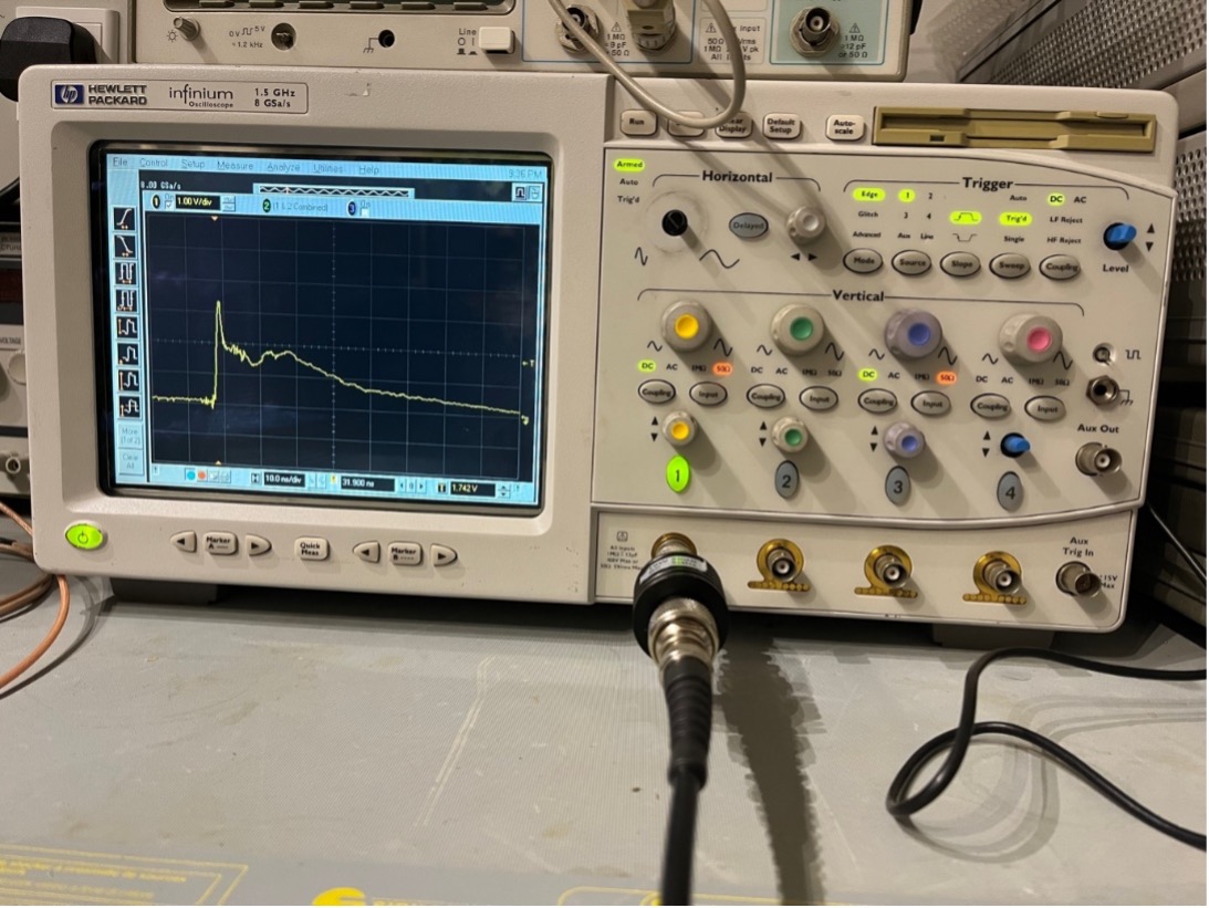
Figure 4. An RG 58 cable with a 20dB attenuator, in fact, showed better results, as one 20dB attenuator has less loss and ringing compared with two 10dB attenuators
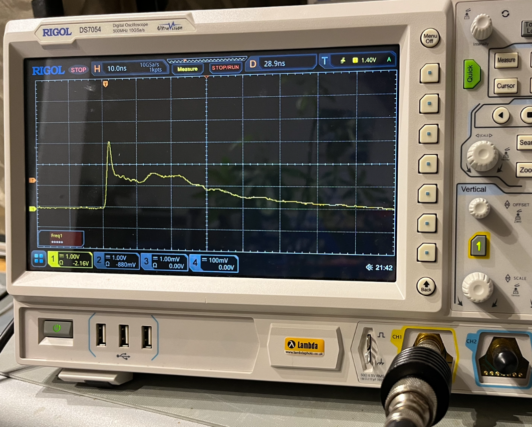
Figure 5. A slower oscilloscope cannot capture the details of an ESD current, however, as a quick sanity check, this may still work, but 500 MHz bandwidth really is the absolute minimum for such tests.
In summary, this approach offers a pragmatic means of quickly assessing the conformity of ESD simulator waveforms, ensuring reliable and efficient troubleshooting in the field of EMC consulting.
References
[1] D. Smith “ Using High Frequency Measurement of ESD Current to Find Problems with an ESD Simulator ”
[2] D. Smith “IEC 61000-4-2 Compliant” ESD Simulators”
[3] D. Smith “Comparison of current waveforms from 150 Ohm and 330 Ohm Networks in an IEC 61000-4-2 Simulator”
Get more from EMC Standards
EMC Standards is a world-leading resource for all things EMC and EMI related. Our website is packed full of both free and paid-for content, including:
- Online quiz
- Webinars
- Training quiz
- And much more!

Electromagnetic Engineering (EMgineering) is the basis for proven good design practices for signal integrity (SI), power integrity (PI), and the control of EMI emissions and immunity (EMC).
Our aim is to help people learn how to more quickly and cost-effectively design and manufacture electronic equipment (products, systems, installations, etc.) to meet functional (i.e. SI/PI) specifications and conform to EMC standards, directives and other requirements.
Such equipment should benefit from reduced warranty costs and financial risks, whilst improving uptime, competitiveness and profitability.
We also cover basic good electrical safety engineering; and the Risk Management of Electromagnetic Disturbances / EMI, whether for Functional Safety or other types of risk.
Join EMC standards TODAY!