Place TVSs before, or after, EMI filters?
03 Apr 2024
Keith's 78th Blog
This is original material was created entirely by a human, on 2nd April 2024
Question:
Hi Keith, I have attended several of your webinars and courses, and recently I have attended the Essential PCB design/layout techniques for good EMC course from the Fedevel Academy and in the short term I also want to attend the Advanced.
First of all, I wanted to thank you for the work you do to disseminate all this very useful information about how to carry out PCB design taking into account all these EMI/EMC concepts that I think we are still far from mastering.
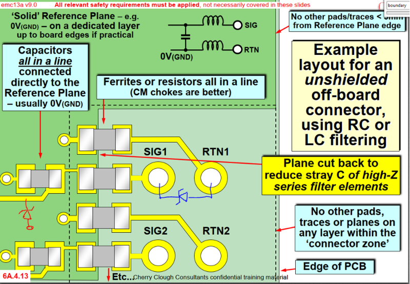
I would like to share with you a question I have about the protection devices (TVS, GDT, MOV...) that are placed at the entrance of a EMZ0/1 boundary zone as soon as they enter from a connector. We are going to give the specific example of an unshielded connector. If we are thinking of introducing a protection device between a specific signal and its return, the question is whether we should put the protection:
- before filtering between the EMZ0/1 zones , between the signal to be protected and its return (TVS in blue)
- or we should put it once inside the EMZ1 zone, after filtering, and between the signal to be protected and the 0V(GND) plane (TVS in red)
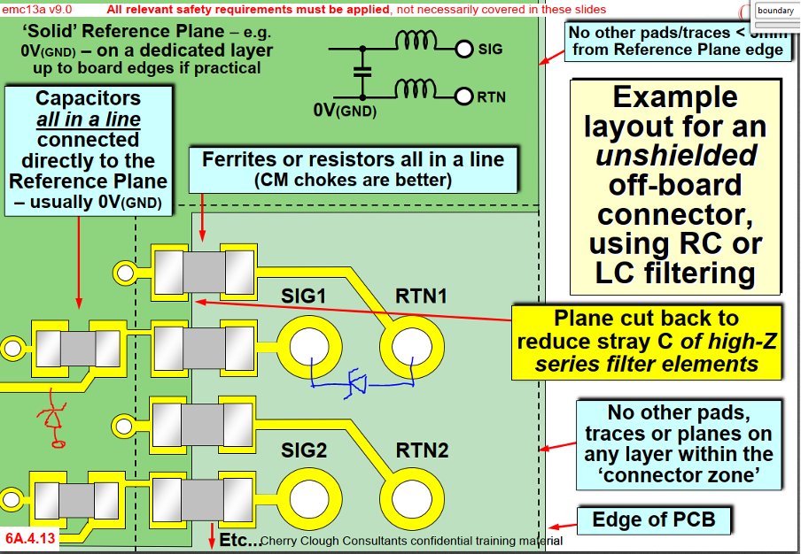
In theory we should place it as close as possible to the connector and before the filters in order to reduce the input inductance that the voltage pulse sees when entering the board. But in that case, I am not sure if the current flow will find an "easy" path to 0V (GND) through the input filtering of the return signal.
My reply:
Hi, and many thanks for your very kind comments about my training!
At least you need my course Module 3 on filtering, and Modules 11 and 12 on Suppressing ESD and Suppressing surges/transients (respectively).
You can buy their colour PDF coursenotes from EMCstandard’s “EMC Academy”, at https://www.emcstandards.co.uk/emc-for-products-equipment2.
Module 3 is also available as a video from https://fedevel.com/instructors/keith-armstrong#courses.
There are three important points to bear in mind:
1) Surge/transient currents don't need to flow to the (so-called) ‘Earth’ or ‘Ground’.
All currents flow in closed loops, even surge and transient currents. Even stray leakage currents.
Where the loops of surge/transient currents include the actual chassis, fuselage, deck, or the soil under a building – like ESD tests assume they do – the consequence of ‘floating’ a circuit from its (so-called) ‘Earth’ or ‘Ground’ is to cause an increase in its static voltage with respect to that ‘Earth’ or ‘Ground’.
This is exactly what happens to cars, aeroplanes, rotorcraft, cellphones, TV remote controls, etc., all the time, and even though they are not ‘earthed’ or ‘grounded’ it almost never causes operational problems.
(But the blades of rotorcraft can create static charges up to 150kV or more, so you should wait until after they have landed before touching any part of them!)
If static charging from ESD, surges, transients, etc., does cause operational problems, electrostatic shielding (with thin metal foils or conductive films) is usually all that is needed.
2) Placing transient suppressors before filters….
When done correctly, this protects the filters from high-voltages that might damage them or spark-over to nearby circuits/components, allowing the use of smaller/cheaper components and smaller PCB assemblies and products.
However, all transient voltage suppression components (other than gas-discharge tubes) have self-capacitance that varies with the applied voltage. The result is that high-enough RF voltages can cause their self-capacitances to vary significantly, long before they start to actually clamp.
In EM environments with high levels of RF fields RF (say, >10V/m), these capacitance variations create non-linear loading that demodulates/intermodulates RF noises and can cause failure to meet the immunity requirements for continuous radiated RF.
(The filters they are protecting will – of course – not suppress the demodulated / intermodulated noises that fall within the passband of the wanted signals/data!)
Yes, it’s rather ironic, that adding surge/transient protection to a filter, should cause radiated immunity requirements to be failed. This is one of the reasons why it is important to meet all immunity requirements, before testing emissions!
3) Placing filters before transient suppressors….
This might be necessary to prevent transient voltage suppression components (other than gas-discharge tubes) from demodulating/intermodulating and causing failure to comply with the requirements for immunity to continuous radiated RF.
The high-voltage filter components needed will be larger (and probably more costly), weigh more and take up more space.
4) Solution? A bit of 2 and 3?
Where there are high levels of RF (say, >10V/m), a simple high-voltage filter placed before the transient voltage suppressors should reduce the RF levels they are exposed to – reducing the demodulated / intermodulated noises created by their voltage-dependant self-capacitances – by enough that they don’t prevent the immunity requirements from being complied with.
Then a low-voltage filter placed after the transient voltage suppressors will allow the immunity requirements to be met.
5) In 1-4 above I have ignored what can be achieved with EM Zoning and shielding.
Cost-effective filtering will not be achieved without maintaining good EM Zone boundaries at the filter’s location, see Module 1 (Physical basis of EMC) and Module 6A on Essential PCB design/layout for EMC.
And cost-effective filtering above 100MHz will not be achieved without using suitably-designed shielding at the EM Zone boundary, also see Module 2 on cable shielding and Module 4 on enclosure shielding.
I hope this helps!
All the very best,
Keith

Keith Armstrong
Director and Principal EMC Consultant, worldwide services
Cherry Clough Consultants Ltd
Cell/text: +44 (0)7785 726 643
Landline/fax: +44 (0)1785 660 247
Emails: keith.armstrong@cherryclough.com
karmstrong@ieee.org
keith.armstrong1@outlook.com
Linked In: Keith Armstrong https://www.linkedin.com/in/keith-armstrong-449801172/
Training, books: https://www.emcstandards.co.uk/online-training
Keith’s Blog: https://www.emcstandards.co.uk/blog
Get more from EMC Standards
EMC Standards is a world-leading resource for all things EMC and EMI related. Our website is packed full of both free and paid-for content, including:
- Online quiz
- Webinars
- Training quiz
- And much more!

Electromagnetic Engineering (EMgineering) is the basis for proven good design practices for signal integrity (SI), power integrity (PI), and the control of EMI emissions and immunity (EMC).
Our aim is to help people learn how to more quickly and cost-effectively design and manufacture electronic equipment (products, systems, installations, etc.) to meet functional (i.e. SI/PI) specifications and conform to EMC standards, directives and other requirements.
Such equipment should benefit from reduced warranty costs and financial risks, whilst improving uptime, competitiveness and profitability.
We also cover basic good electrical safety engineering; and the Risk Management of Electromagnetic Disturbances / EMI, whether for Functional Safety or other types of risk.
Join EMC standards TODAY!