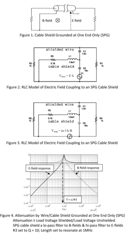
Figure 4 is the combined results of the two coupling models. The effect of the SPG shield is exactly what the RLC model suggests; that is, the SPG shield is a low pass filter for magnetic fields and a high pass filter to electric fields. The filters’ break points are both at the frequency corresponding to the shield length being one quarter wavelength. The SPG shield is therefore not a shield at all. Shielding effects are orders of magnitude below these curves. The last point is that the
SPG resonates so that the induced signal is amplified, not attenuated, at the shield’s resonant frequency. This model is a low frequency model however all of the relevant parameters are included.
The multitude of app notes and articles on this subject that recommend grounding the shield at one end only misrepresent the physics of shielding and falsely ascribe a ground loop to the shield where the circuit itself was part of the original ground loop. Cable shielding and ground loops must be disassociated. Grounding the shield at both ends attenuates the coupling to the shielded wires by approximately the ratio of load current to shield current, SA ≈ Iload/Ishield ≈ ZT·l/2·Zload,
where ZT is the shield transfer impedance, l is the length, and Zload is the load resistance of both loads. As an example, a cable shield with a DC resistance (and low frequency transfer impedance, ZT·l = Rdc) of 1Ω and load resistances of 1kΩ will have a low frequency shield attenuation of approximately 5·10-4 or 66dB.
The shields should be “bonded’ to the boxes at the ends of their respective cables, not earth ground, building ground, or anything else. Military standards like Mil-Std-188-124B and the FAA get it right. It’s time for everyone else to also.
The following is litany of very bad advice from otherwise reputable sources:
(1) EE Times, “Control System Grounding - Part 2: Ground Wiring, Shield Grounds, and Power Supply Grounding, Shield Grounds”, Roger Hope, Dave Harrold, and David Brown, 7/15/2008: A proper shield ground path is to ground the shield at one end only.
(2) EDN, “Grounding and Shielding: No Size Fits All”, Martin Rowe, Senior Technical Editor - August 1,2001; Never connect a shield to ground at both ends. Doing so would create a ground loop.
(3) Analog Devices, Analog Dialogue 17-1, 1983, Alan Rich, “Shielding and Guarding, How to Exclude Interference-Type Noise, What to Do and Why to Do It – A Rational Approach”: Don’t connect both ends of the shield to ground.
(4) Wikipedia, Shielded Cable: The common method to wire shielded cables is to ground only the source end of the shield to avoid ground loops. Wikipedia!!??
(5) LTC486 Data Sheet: The optional shields around the twisted pair help reduce unwanted noise, andare connected to GND at one end.
(6) Maxim Integrated, TUTORIAL 2045, Understanding Common-Mode Signals: For any shielded pair(s) carrying balanced signals, you should connect the shield to ground at one end, usually the receiving end.
(7) web www.bobtech.ro, Wiring Guidelines for RS-485 Networks, Application Note 001, Grounding: If shielded twisted pair cable is used… , the shield shall be connected to earth ground only at one end. (8) B & B Electronics, RS-422 AND RS-485 APPLICATIONS EBOOK, Shielding: If shielded cable is used, the shield should be grounded at one end only, preferably to earth ground.
(9) Alpha Wire, www.newark.com/pdfs/techarticles/alphawire/ USC.pdf, Understanding Shielded Cable:Ground the cable at one end. This eliminates the potential for noise inducing ground loops.
(10) eeeic.eu/proc/papers/ 55. pdf , Cottbus University of Technology, Germany & Wroc?aw University of Technology, Poland, Anke Fröbel, “Cable Shielding to Minimize Electromagnetic Interference”, III. CABLE SHIELD GROUNDING: If a shielded cable is used to connect two systems, the shield has to be connected to a single ground reference. In order to prevent that electromagnetic energy penetrates through the shield, the outer surface of the shield has to be grounded. At low
frequencies for E-field excitation it is more efficient to ground both ends, whereas for H-field excitation one end grounding has to be favored, since this eliminates the formation of a current loop by the cable and the ground plane. At high frequencies both ends grounded configurations avoids resonances for E-field and H-field excitations. In practice one ground connection is often preferred, since this avoids ground loops. However, for short cables, at low frequencies, the voltages induced by EMI at both ends of a coaxial cable become nearly equal and one end grounding
is needed for E-field as well as for H-field excitations. [I included this to show how confused people are about this subject. The author tried to write about shielding but only displayed his ignorance of the subject. He even got the E-field and H-field shielding reversed.]
(11) www.calex.com/pdf/4ground_shield.pdf, This article was written for CALEX by Mr. Ralph Morrison, President of INSTRUM and the author of Grounding and Shielding Techniques in Instrumentation published by Wiley; Grounding and Shielding: The input cable shield cannot be grounded more than once. [With figures, only, Mr. Morrison shows the other end of a cable shield connected to ground
through a 10MΩ resistor. “From the jaws of victory…”]


